Digital Electronics
It is a sub-branch of electronics that deals with digital signals. Used in large applications from high-end processor circuits to miniature circuits for signal processing, communication, etc.
It is preferred over analog signals for its performance, accuracy, speed, immunity to noise, etc.
Analog and Digital Signal
Analog signal is varying voltage or current with respect to time. Analog signals used rectifying circuits and transistor amplifier circuits. Digital signals are the one that contains only discrete values of voltages.
Digital signals need two states to switch ON and OFF. ON is considered as one state and OFF is considered as the other state.
It is also defined as a high (on) or low (off) state, closed (on), or open (off). These high and low states are defined using binary numbers 1 or 0 in Boolean Algebra.
1 is on and 0 is off.
Logic Gates
It is an electronic circuit that functions on digital signals. It is the basic building block for the digital system. It has one output with one or more than one input.
There are three basic types of logic gates: AND Gate, OR Gate, and NOT Gate. The other Logic gates are Ex-OR, NAND, and NOR. These logic gates are constructed from the basic logic gates.
Digital electronics deals with the logical operation. The variables are called Logical variables. The operators like logical addition (+) and logical multiplication (.) are called logical operators.
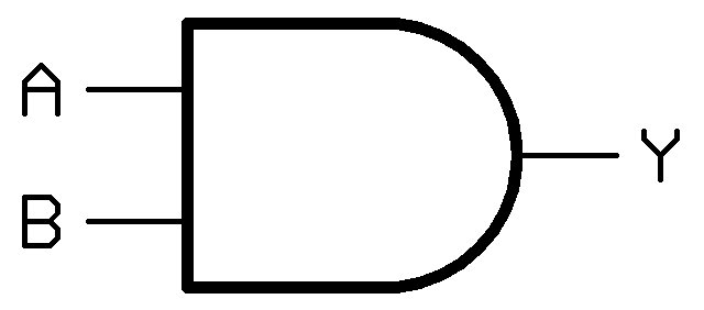
AND Gate
| Input | Output | |
| A | B | Y= A.B |
| 0 | 0 | 0 |
| 0 | 1 | 0 |
| 1 | 0 | 0 |
| 1 | 1 | 1 |
Boolean Equation for And is Y = A.B
We get output 1 only if both the inputs are 1. Otherwise, we get 0 as output.
OR Gate

| Input | Output | |
| A | B | Y= A+B |
| 0 | 0 | 0 |
| 0 | 1 | 1 |
| 1 | 0 | 1 |
| 1 | 1 | 1 |
Boolean Equation for And is Y = A + B
We get output 1 if either one of the inputs is 1.
NOT Gate

| Input | Output |
| A | Y = Ā |
| 0 | 1 |
| 1 | 0 |
The boolean equation is Y = Ā.
If the input is 1 then the output is 0. If the output is 0 then the input is 1. This gate is also called Inverter.
Nand Gate
AND Gate plus NOT Gate is NAND Gate. The output of AND is given as the input to NOT Gate.


NOR GATE
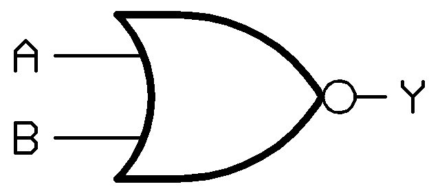

The output of the OR gate is given as input to Not.
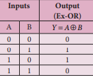
Ex-OR Gate